Auto-Ranging Ohmmeter
For this project, me and my partner created auto-ranging ohmmeter that can calculate and display any load resistance of 1Ω to 1MΩ. In this project, I was able to learn how to work with embedded systems, how to design and create a PCB, and how to design, test, and implement a working circuit.
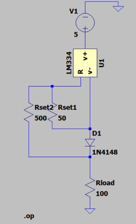

LTSpice Design
As part of the design for our ohmmeter, we had to simulate our circuit using LTSpice - an electrical circuit simulation software. For the circuit of our ohmmeter, we used the zero-temperature coefficient circuit shown in the datasheet of the LM334Z by National Semiconductor. This is because the circuit provided will give us a constant current source without any temperature coefficient affecting it. Note that the LM334Z will be our constant current source for our ohmmeter, which will help us solve for the load resistor value later on for our auto-ranging ohmmeter.
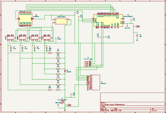

Kicad PCB Schematic
In order to make the PCB for the auto-ranging ohmmeter, we had to create a full schematic of the circuit on Kicad - a website used to make PCBs. For the schematic, we had to find all the symbols for our parts such as the resistors, ADC, Arduino Uno, Constant Current Source (LM334Z), Switches/Relays (HE721A0510), driver (ULN2803), and LCD display. During this stage, we also had to choose the footprints dedicated for each symbol in the schematic in order to create a PCB Layout later on.
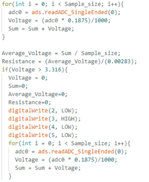

Arduino Code
Because we are using an Arduino as our microcontroller for our ohmmeter, we will need to code for functions of all the parts using the Arduino IDE. This includes coding for the LCD display of the given resistance, the ADC to convert our analog signal to digital so we can use it in the code for calculations, and the relays switches to switch on and off depending on the voltage drop of the load resistor. A small snippet of the code can be seen to the right which showcases a for loop in which we used to collect the samples of the resulting resistance calculated in order to display the most precise and accurate results. The small snippet of code also shows the start of how the relay switches are implemented.
For full code refer to Azzu000/Ohmmeter-Arduino-Code: Contant Current Auto-ranging ohmmeter code for Arduino (github.com)
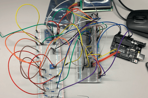

Bread Board Testing
Before we commit and create the PCB layout, we have to do some testing with the code. To do this we had to use two bread boards and connect the whole circuit together along with the Arduino and LCD display. Due to the number of components, the wiring was a bit messy but with different color wires we were able to keep track of where the wires are connected to. We used a multimeter to test the voltage, current, and the actual values of all our resistors - specifically the voltage drop of our load resistor and the constant current of our constant current source given different resistors.

PCB Layout
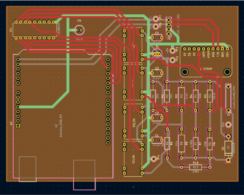
After thorough testing, we finally created our PCB layout. In order to create a good PCB, we followed many of the PCB guidelines and tips given by our professor. We end up creating a four-layer PCB which includes the ground, the 2 layers of wire connections, and the power layer. A four-layer PCB will allow us to overlap wire connections. This can help when we have too much wire connections and can help simplify the process of creating our PCB layout in general. The different color of the wires shown in the PCB layout shown to the right represents the different layers of the PCB as well.

Final Product
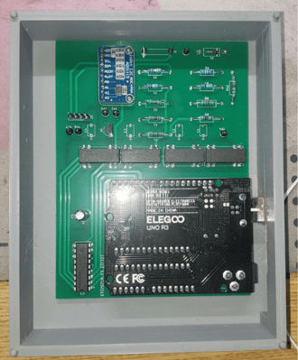
After receiving our PCB order from JLCPCB, we soldered all our electrical components to our PCB. The final PCB with the components soldered on can be seen to the left. We made sure to test the final PCB to make sure the results are as expected, and everything is working properly. To do this we used a multimeter on the different test points created on the PCB. The results of the PCB were more stable than the test results of the bread board which is to be expected. We made sure the final product meets all the requirements such as being able to measure the resistance of 1Ω to 1MΩ automatically.
Projects
Showcasing my computer engineering major projects on website.
© 2024. All rights reserved.
Contacts
Email: ruiqihuang55504@gmail.com
Phone: 1(206)886-2017
LinkedIn: https://www.linkedin.com/in/ruiqi-huang-033441252/
